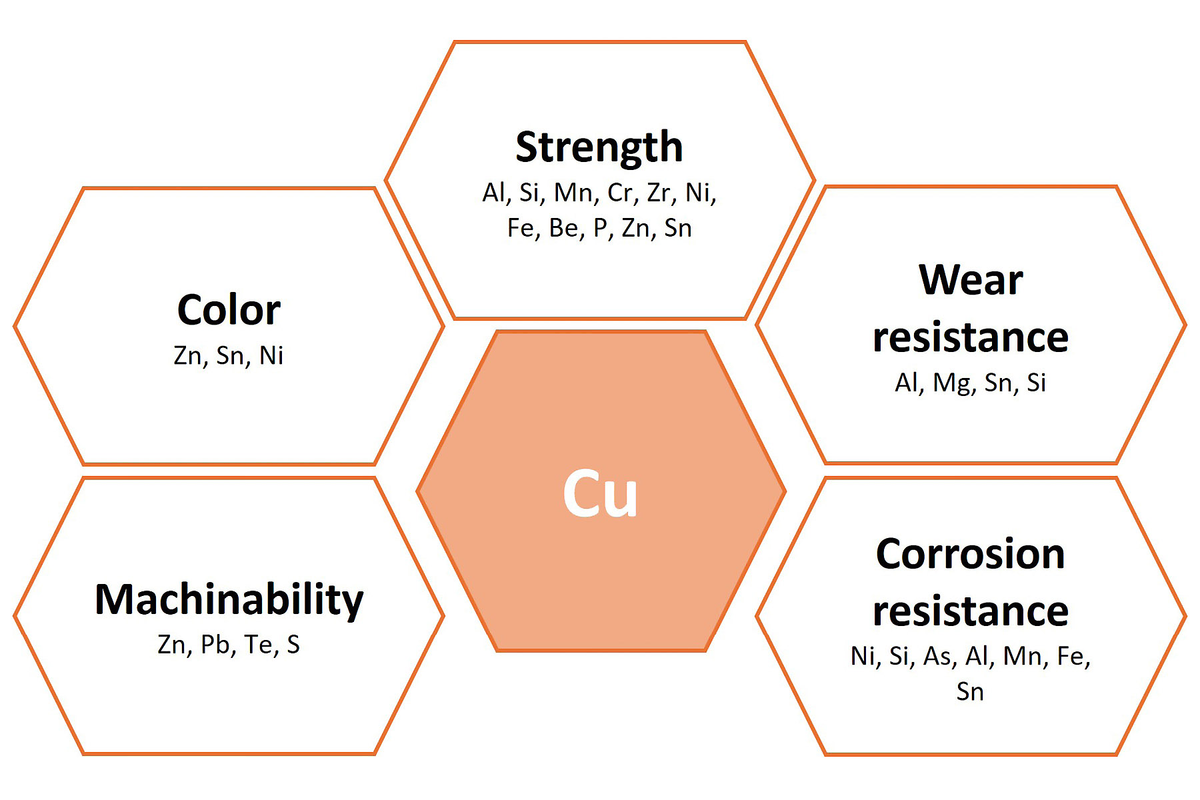
Copper is soft and ductile: easy to work with, yet prone to surface damage during preparation. Its unique combination of properties, especially its exceptional electrical and thermal conductivity, makes it the material of choice in applications such as electrical wiring, telecommunications, heat exchangers, and kitchenware. Copper also plays a crucial role in the energy transition, being indispensable in technologies like wind turbines, solar panels, and electric vehicles. Its warm, attractive appearance further makes it popular for decorative and functional items like handles, doorknobs, countertops, and tables.
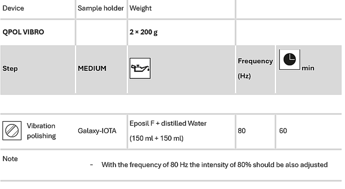
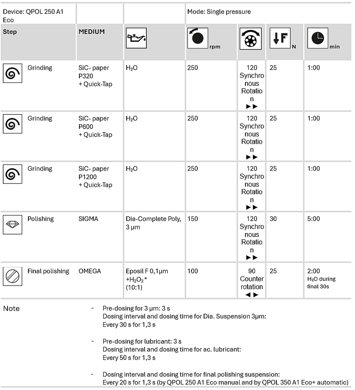
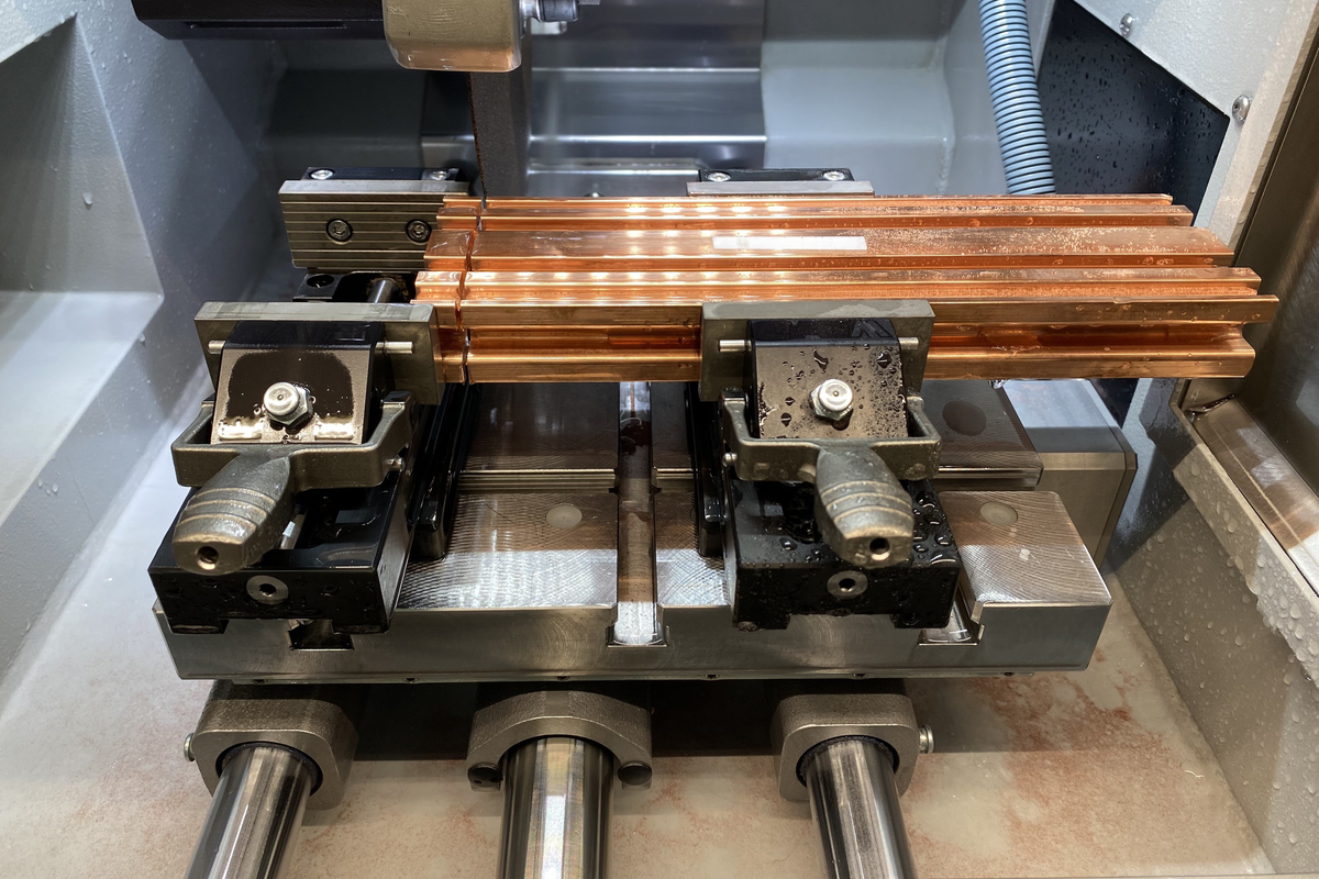
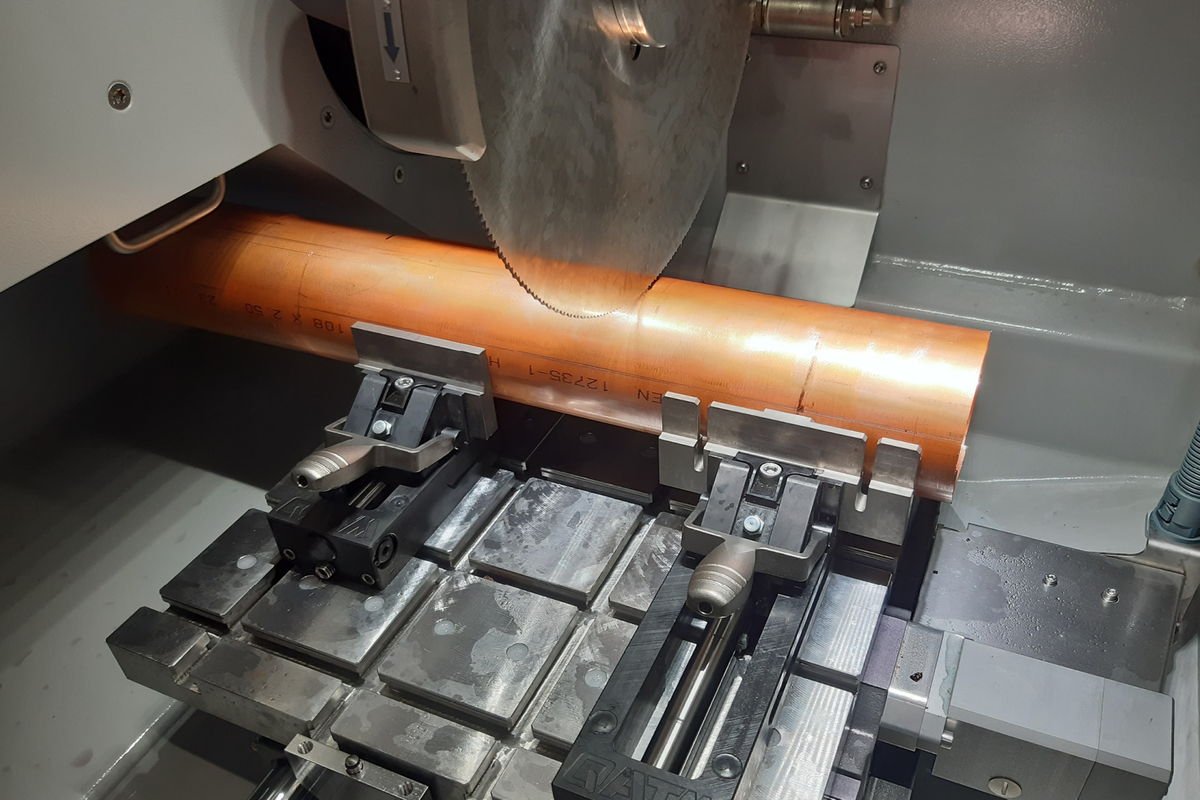
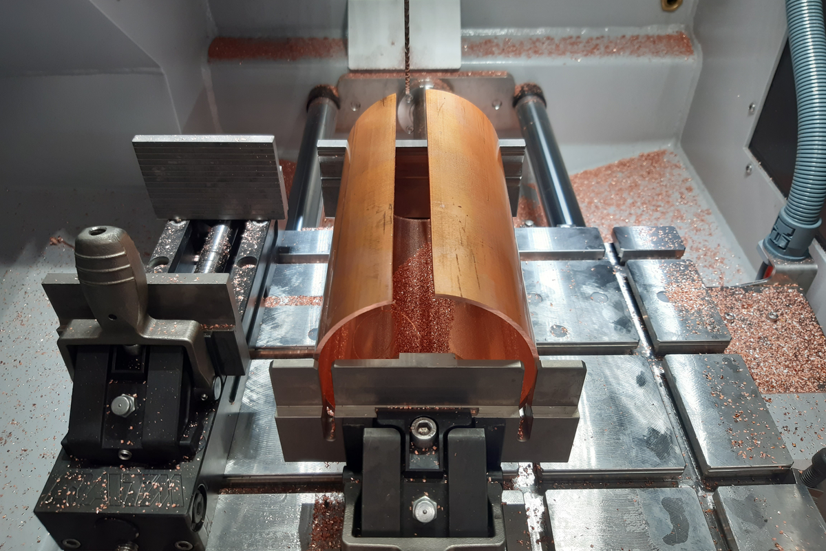
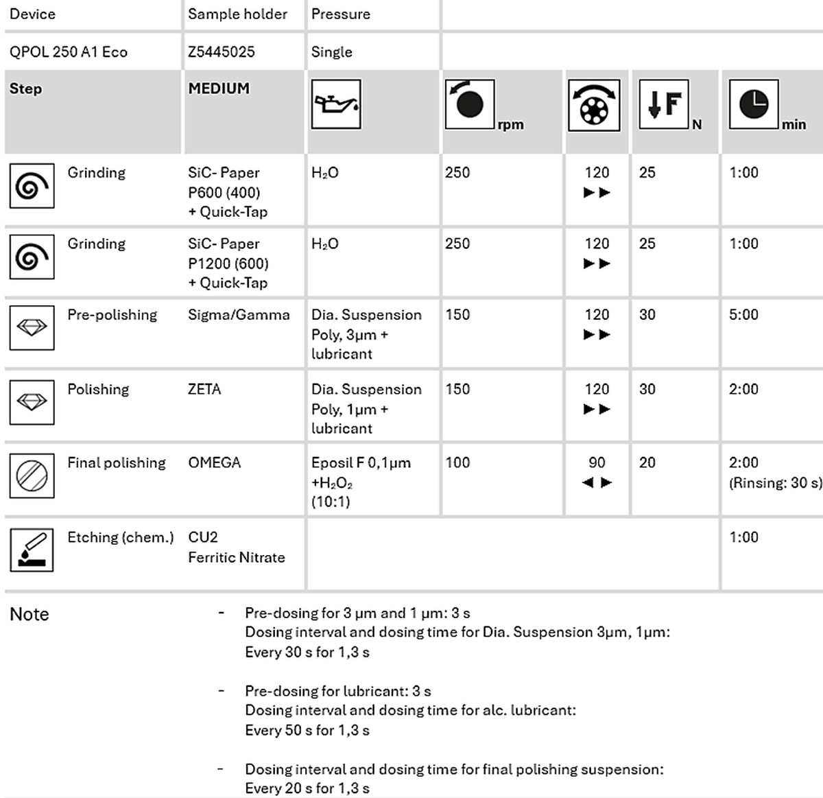
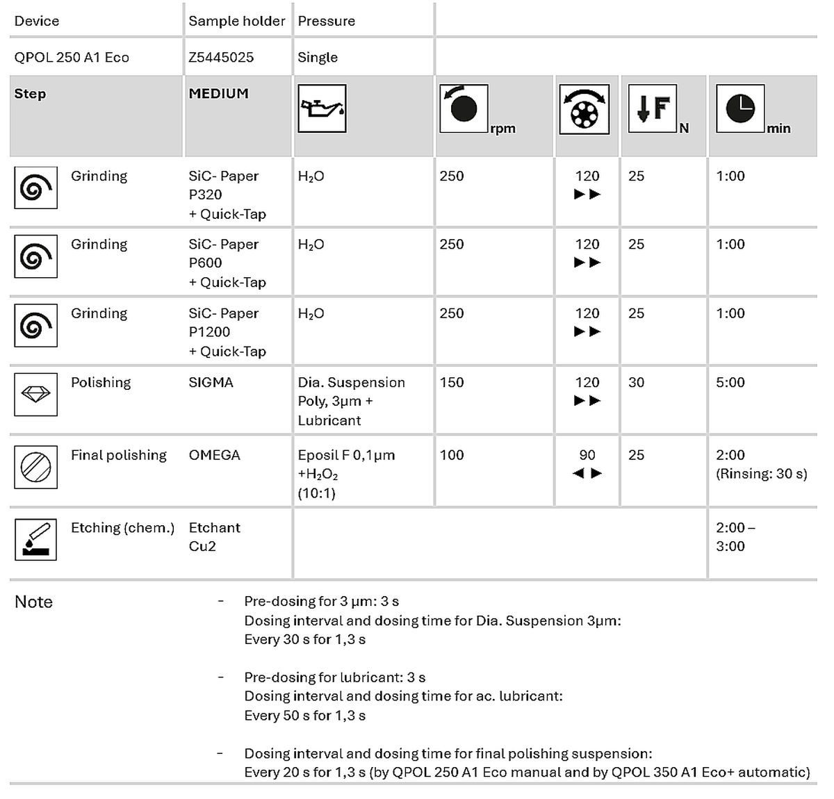
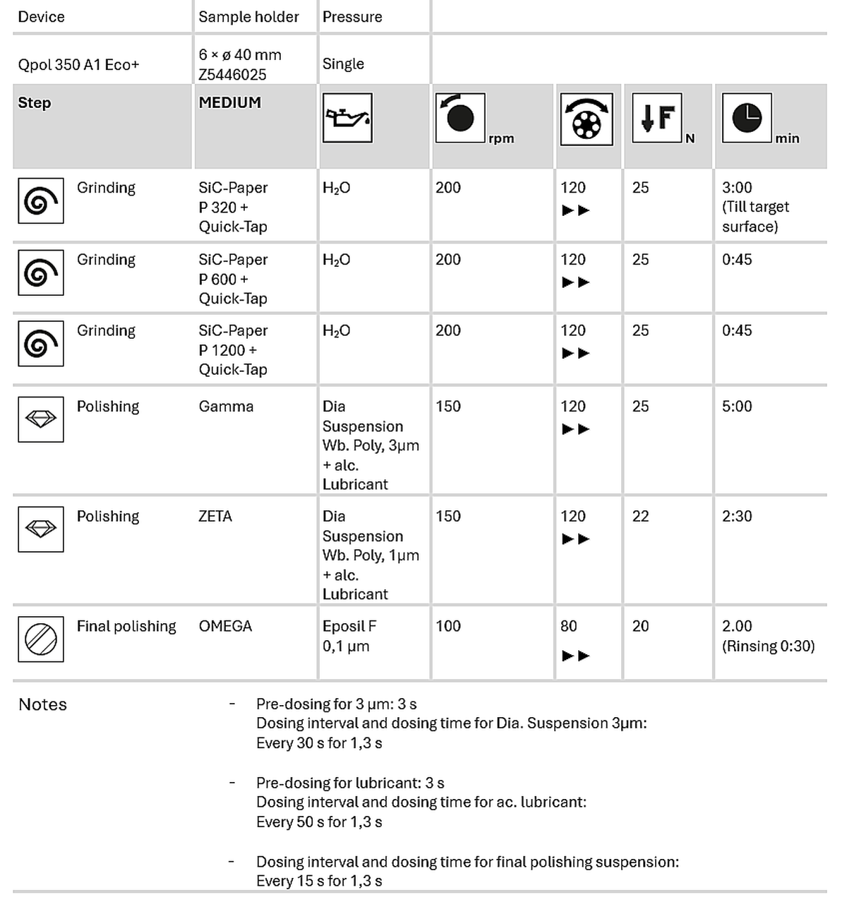
To accurately assess the microstructure of copper, careful metallographic preparation is essential, as improper handling can easily introduce artifacts like smearing or scratches caused by oxide pull-out. This guide walks you through each step in the metallographic preparation of copper and its alloys, from cutting and mounting to grinding, polishing, and etching.

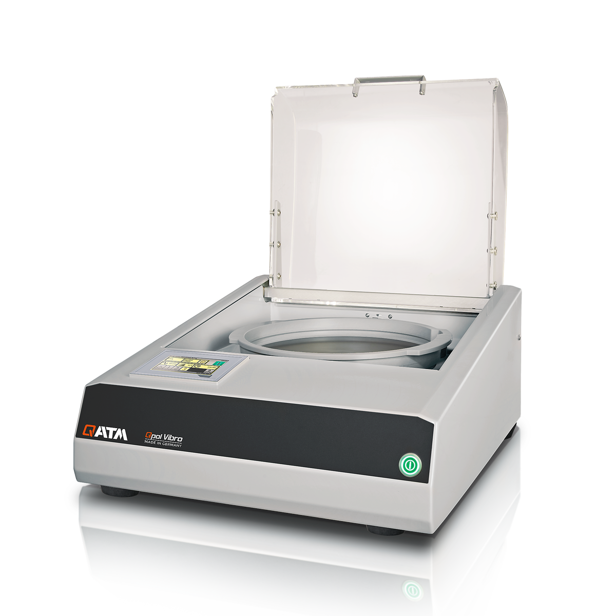
QATM offers products for all materialography applications


 – 200x")


 – 200:1")
 – 500:1")


 – 500:1")


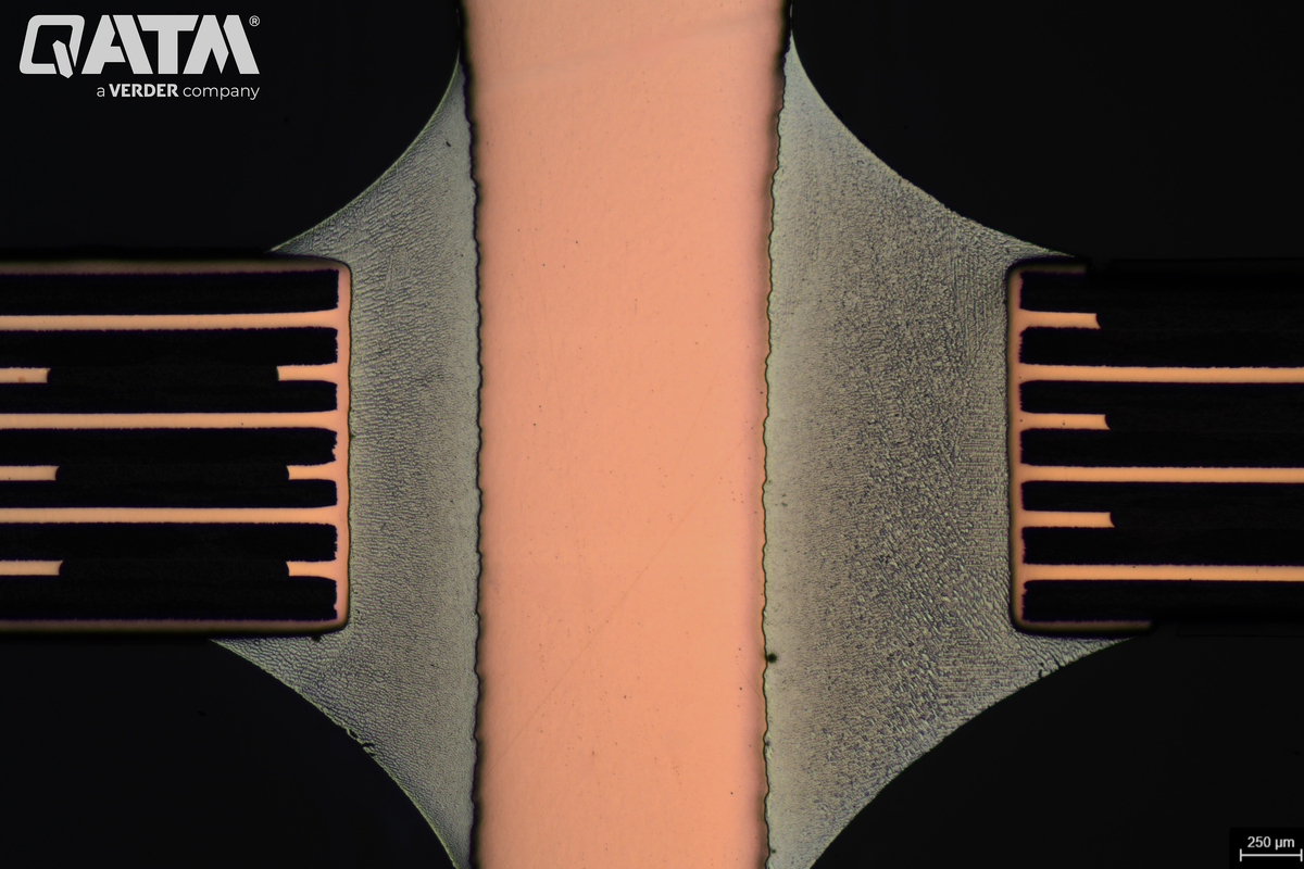


 after vibration polishing")